Description of L293D
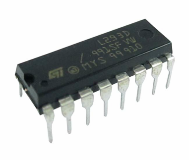
L293D is a motor driver IC which can allows 2 DC motors on either direction. I is a 16 pin IC, both of its side have 8 pin.
This IC works in the concept of H-bridge.
What is H-bridge?
Ans:- H-bridge is a circuit which allows the voltage to be flown in either direction. As you know voltage need to change its direction for being able to rotate the motor in clockwise or anticlockwise direction, Hence H-bridge IC are ideal for driving a DC motor.
In a single L293D chip there two H-bridge circuit inside the IC which can rotate two dc motor independently.
Given below is the pin diagram of a L293D motor controller.
There are two Enable pins on L293D. Pin 1 and pin 9, for being able to drive the motor, the pin 1 and 9 need to be high. For driving the motor with left H-bridge you need to enable pin 1 to high. And for right H-bridge you need to make the pin 9 to high. If anyone of the either pin 1 or pin 9 goes low then the motor in the corresponding section will suspend working.
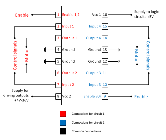
There are 4 input pins for L293D, pin 2,7 on the left and pin 15 ,10 on the right as shown on the pin diagram. Left input pins will regulate the rotation of motor connected across left side and right input for motor on the right hand side.
L293D works on logical inputs i.e 0 and 1.
NOTE it down that L293D use its pin 16 to fulfill its own requirements, this means that for its internal operations it require some voltage around 5V, so it uses pin 16 to acquire those 5V form the DC power source.
It uses pin 8 to acquire the output voltage, this means that pin 8 takes output voltage from the DC power source and distribute it parallely. The maximun voltage it can take is from 5V - 36V
For more details of this topic click on the link:-http://chillyprojects.blogspot.in/2016/05/how-l293d-works.html
THANK YOU VERY MUCH FOR READING MY BLOG, STAY BLESSED AND BE READY FOR MY NEW BLOG.