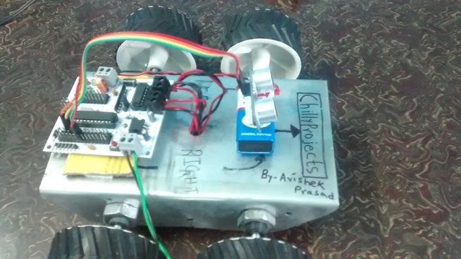
This blog contains full details of each and every part of this robot as well as whole process of involve in assembling this robot.
So here I start.
COMPONENTS REQUIRED :-
1. Ultrasonic Sensor
To make this robot I am using HC-SRO4 ultrasonic sensor, I personally recommend you to use a ping ultrasonic sensor rather than this sensor, because you all will feel a bit comfortable with a ping as it only have 3 pins. CLICK HERE to achieve more knowledge on a ultrasonic sensor.
2. Arduino Uno Board
I have used this hybrid arduino board to make this robot. It's name is "roboBoard 1", made in India and manufactured by Skubotics. It have lots of advantage on the original Arduino board. The main advantage of this arduino board is that it have internally mounted motor driver.
The motor driver contains a dual motor controlling IC. The name if this IC is L293D.
Schematic of L293D
Let me tell you that all pins of L293D is internally connected to the arduino
L293D Arduino
2 D5
8 D6
1 D9
15 D7
10 D8
9 D10
If you are using a real arduino uno board then you can connect the motor driver IC L293D with it using the above pin configuration. If you use this configuration then you will not face any error during program while compiling.
You need to connect pin 16 to the Vcc(5V) of arduino.
CLICK HERE to grab full knowledge on L293D.
3. Jumper cables
For this robot I required only 4 jumper cables, only to connect HC-SRO4 sensor with arduino else every components are internally connected.
4. Dual side foam tape
This tape is highly recommended to stick one component with the other one.
5. AC adapter (9V DC, 0.5A)
This AC adapter converts rectify 230V AC to 9V DC and gives 0.5 A current as an output.
We require this to power up the arduino.
6. 9V DC Battery
We require this to supply voltage to the motor.
7. Battery cap
8. Wires
9. scissors
We require this to sharp the wires ends.
10. Screw driver/ Tester
11. USB to serial uploader
This uploader is required to connect arduino with a computer.
12. Computer
13. Chassis
14. DC Geared motors (12V, 200 RPM)
15. Gripped wheel
Mentioned above are the list of all the components and apparatus which are necessary to make this robot.
Procedure to make this robot
STEP 1 :-
Assemble all the motors and wheels in the chassis. In this robot I am using 4 motors and correspondingly 4 wheels.
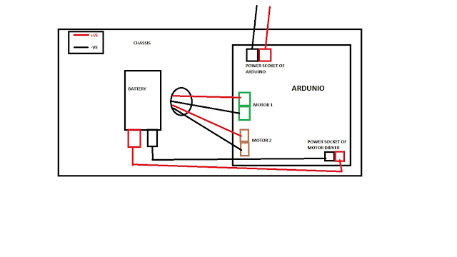
The two left side motors and the two right side motors are connected in series.
Thus the two left side motors acts as a single load, similar to the right side motors.
STEP 2:-
Take a piece of card board and paste it on the chassis using dual side foam tape. It will prevent the arduino board to get sorted as the chassis is made up of metal.
Now paste the arduino board on the card board.
STEP 3:-
Paste the 9V DC battery in front of the robot using dual side foam tape.
STEP 4:-
Connect all wires according to the given schematics.
STEP 5:-
Paste the HC-SRO4 sensor on the battery using dual side foam tape.
STEP 6:-
Now connect the HC-SRO4 sensor to the arduino using jumper cable
connection configuration:-
HC-SRO4 ARDUINO
Vcc 5v
GND GND
TRIG D12
ECHO D11
Now the assembling and connection parts are over.
STEP 7:-
Now connect the Arduino with the computer using the USB serial uploader and start programming.
Attention required:- firstly you need to check weather the left motors and right motors are configured correctly or not. For just checking purpose program your arduino using this code.
----------------------------------------------------------------------------------------------------------------------------------------------------------------------------------------------------------------------------------------------------
// Code by Avishek Prasad.
// Visit https://chillyprojects.weebly.com
// This code is for testing the Motor
// Just copy it from here and paste it
// Contact me if this doesn't work
const int lm1 = 5;
const int lm2 = 6;
const int lspeed = 9;
const int rm1 = 7;
const int rm2 = 8;
const int rspeed = 10;
// Above is the motor driver pin connection. LM1 and LM2 are the
// digital input pins from arduino to the motor driver. Same for
// RM1 and RM2 and lspeed and rspeed are the enable pins.
// Change accordingly.
int spd=255;
// Above sets the speed of the bot
void setup()
{
pinMode(lm1, OUTPUT);
pinMode(lm2, OUTPUT);
pinMode(rm1, OUTPUT);
pinMode(rm2, OUTPUT);
pinMode(lspeed, OUTPUT);
pinMode(rspeed, OUTPUT);
analogWrite(lspeed, spd);
analogWrite(rspeed, spd);
Serial.begin(9600);
}
void loop()
{
digitalWrite(lm1,HIGH);
digitalWrite(lm2,LOW);
digitalWrite(rm1,HIGH);
digitalWrite(rm2,LOW);
}
// After uploading this code in the arduino you
//will observe that each and every motor
//are rotating in forward direction.
// If this doesn't happens then check the motors connection properly
----------------------------------------------------------------------------------------------------------------------------------------------------------------------------------------------------------------------------------------------------
Above was the code for testing that motor is working fine or not, or each and every connections are correct or not.
If every thing works fine then after this you need to upload the main program.
----------------------------------------------------------------------------------------------------------------------------------------------------------------------------------------------------------------------------------------------------
// Code by Avishek Prasad.
// Visit https://chillyprojects.weebly.com
// This code is for a OBSTACLE AVOIDING ROBOT
long cm, duration;
const int echoPin = 11;
const int trigPin = 12;
const int lm1 = 5;
const int lm2 = 6;
const int lspeed = 9;
const int rm1 = 7;
const int rm2 = 8;
const int rspeed = 10;
// Above is the motor driver pin connection. LM1 and LM2 are the
// digital input pins from arduino to the motor driver. Same for
// RM1 and RM2 and lspeed and rspeed are the enable pins.
// Change accordingly.
int spd=255;
// Above sets the speed of the bot
void setup()
{
pinMode(lm1, OUTPUT);
pinMode(lm2, OUTPUT);
pinMode(rm1, OUTPUT);
pinMode(rm2, OUTPUT);
pinMode(lspeed, OUTPUT);
pinMode(rspeed, OUTPUT);
pinMode(trigPin, OUTPUT);
pinMode(echoPin, INPUT);
analogWrite(lspeed, spd);
analogWrite(rspeed, spd);
Serial.begin(9600);
}
void loop()
{
// below code chunk calculates
// the distance ahead using an ultrasonic sensor
digitalWrite(trigPin, LOW);
delayMicroseconds(2);
digitalWrite(trigPin, HIGH);
delayMicroseconds(5);
digitalWrite(trigPin, LOW);
duration = pulseIn(echoPin, HIGH);
// convert the time into a distance
cm = duration/29/2;
Serial.print(cm);
Serial.println(" cm");
if(cm < 20)
{
go_back();
delay(1000);
go_left();
delay(2000);
}
else
{
go_straight();
}
}
// Here are the functions that are used in the program
void go_straight()
{
digitalWrite(lm1,HIGH);
digitalWrite(lm2,LOW);
digitalWrite(rm1,HIGH);
digitalWrite(rm2,LOW);
}
void stop_bot()
{
digitalWrite(lm1,LOW);
digitalWrite(lm2,LOW);
digitalWrite(rm1,LOW);
digitalWrite(rm2,LOW);
}
void go_left()
{
digitalWrite(lm1,LOW);
digitalWrite(lm2,LOW);
digitalWrite(rm1,HIGH);
digitalWrite(rm2,LOW);
}
void go_right()
{
digitalWrite(lm1,HIGH);
digitalWrite(lm2,LOW);
digitalWrite(rm1,LOW);
digitalWrite(rm2,LOW);
}
void go_back()
{
digitalWrite(lm2,HIGH);
digitalWrite(lm1,LOW);
digitalWrite(rm2,HIGH);
digitalWrite(rm1,LOW);
}
// You can use any of the above functions according to your necessity.
//Enjoy with this new robot
----------------------------------------------------------------------------------------------------------------------------------------------------------------------------------------------------------------------------------------------------
for more details on this robot visit this link:-
http://chillyprojects.blogspot.in/2016/05/how-to-make-obstacle-avoiding-robot.html
I will upload a video on this topic very soon in youtube
please subscribe to my channecl :-
https://www.youtube.com/channel/UCcCLvXs7C2Rgq8EKCQFIuGw
Like my facebook page:- https://www.facebook.com/chillyprojects/
download my app for easy connectivity
Android :-http://snappy.appypie.com/media/appfile/41737342dd9e.apk
Iphone:- http://snappy.appypie.com/…/download-pli…/appId/41737342dd9e
THANK YOU VERY MUCH FOR READING MY BLOG, STAY BLESSED AND BE READY FOR MY NEW BLOG.